Hollow Wooden Surfboard
Overview
Design
Simulation
Manufacturing
The goal of this project was to build the perfect road trip board. I wanted a board that was small enough to fit side-by-side with a sleeping platform in the back of my car while also being streamlined and buoyant enough to surf small waves like a longboard.
_edited_edited.jpg)
For this board, I wanted to prioritize paddling speed (the speed at which you travel while trying to catch a wave) in order to surf smaller conditions.
Because fish style surfboard (split tail) are known to be the best shortboards for small waves, that I where I started my design. I ended up designing multiple variations of a 6'0" board to simulate using computational fluid dynamics (CFD) software.


With the exterior surface modeling complete, it was time to design the interior frame structure. I had ample supply and easy access to baltic birch plywood which was both strong and easy to machine. I also had access to a small scale CNC router in order to cut the ribs. To ensure that the ribs were spaced properly, I constructed a test section and stood on it with my whole weight (worst use case).
The tail and nose on hollow surfboards are typically large, rectangular blocks that are hand shaped to match the rest of the board. I decided to utilize the CNC router and cut sections of baltic birch to minimize the amount of hand-shaping required.

In order to maximize the board's paddling speed, I ran computational fluid dynamics (CFD) simulations over multiple board designs. The goal of this was to minimize the drag experienced by the board when paddling for a wave.
On each of the board designs, it was necessary to estimate a waterline. By assigning a density to the materials in the CAD model and using my weight as a point load on the center of the board, I was able to use planes to split the model exactly where the theoretical waterline would be.
Using this waterline, I ran two phase simulations in ANSYS Fluent. The drag forces between the various boards were compared, and the design with the lowest drag was selected.

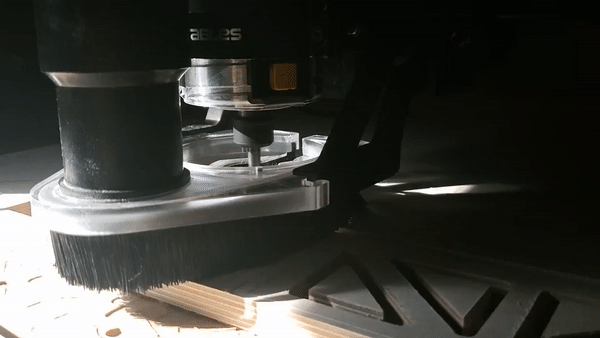
The entire internal rib structure was cut using a CNC router. Due to the bed size of the CNC, the stringer (or centerline rib) had to be split into sections.
The nose and tail were also machined on the router. The rib structure is made out of Baltic Birch plywood due to its availability, strength, and my personal familiarity with CNC routing it.
After cutting the parts on the CNC, the rib structure was assembled and glued.


The tail and nose were added, and the whole structure was glued to 1/4" sheets of wood for the bottom. The boards on the bottom had to be steam bent to adhere well to the ribs. The first rail strips were also steam bent and glued into place.

And after a few more ribs and some sanding...


And gluing the top deck...


And finally painting, fiberglassing, and adding the fins...

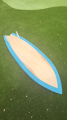
This project took a huge amount of time, but was worth every second. This project required me to learn CFD and surface modeling while putting my DFMA, composite, and woodworking experience to the test. I unfortunately don't have any pictures of surfing it yet, but those should be coming soon...